.jpg)
Tabletop Conveyors
Intermediate Sections
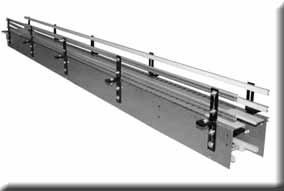 An intermediate section is the section of the conveyor that transports the product between the drive and idle end.
- 5 1/2” deep frame
- UHMW clip on wearstrip
- Adjustable guide rail
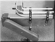
Curves
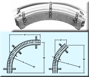 A curve is used to change conveyor direction with a continuous motion, utilizing side flexing chain. This direction change occurs without the use of a deadplate or an additional drive.
- Lubricated UHMW inside wearstrips
- Option for Nylatron wearstrip (Recommended for speeds above 128 fpm)
- 5 1/2” deep frame
- Radius is measured to centerline of chain (inside chain on dual wide)
- 0’ – 6” striaght at each end
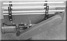
Idle End Assemblies
 The idle end assembly is the beginning point of the conveyor where the return chain is now the carrying chain.
- 3’ – 0” O.A.L. with standard below motor mount
- 8” deep frame
- Finger guard included.
Motor/reducer sold separately.
Drive End Assemblies
 The drive end is the ending point of the conveyor where the motor is located. The product carrying chain becomes the return chain.
- Lubricated UHMW inside wearstrips
- Option for Nylatron wearstrip (Recommended for speeds above 128 fpm)
- 5 1/2” deep frame
- Radius is measured to centerline of chain (inside chain on dual wide)
- 0’ – 6” striaght at each end.
Deadplate Turns
 A deadplate turn is used to change conveyor direction by 90 degrees utilizing straight running chain. This type of direction change requires the use of a deadplate and an additional drive. Speed changes can be made at this point. Back pressure is required to make the transfer across the deadplate.
- 3’-0” x 1’-0” O.A.L. with standard below motor mount (325, 450, 750)
- 4’-0” x 1’-0” O.A.L. with standard below motor mount (1500)
- 8” deep frame
- Adjustable stainless steel deadplate
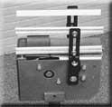
Parallel Transfers
- 4’ – 0” O.A.L. with standard below motor mount (325, 450, 750)
- 5’-0” O.A.L. with standard below motor mount (1500)
- Minimum 1/16” gap between chains
- 8” deep frame


